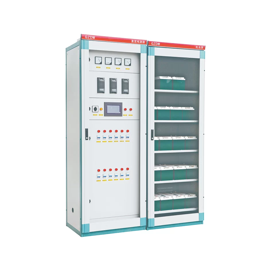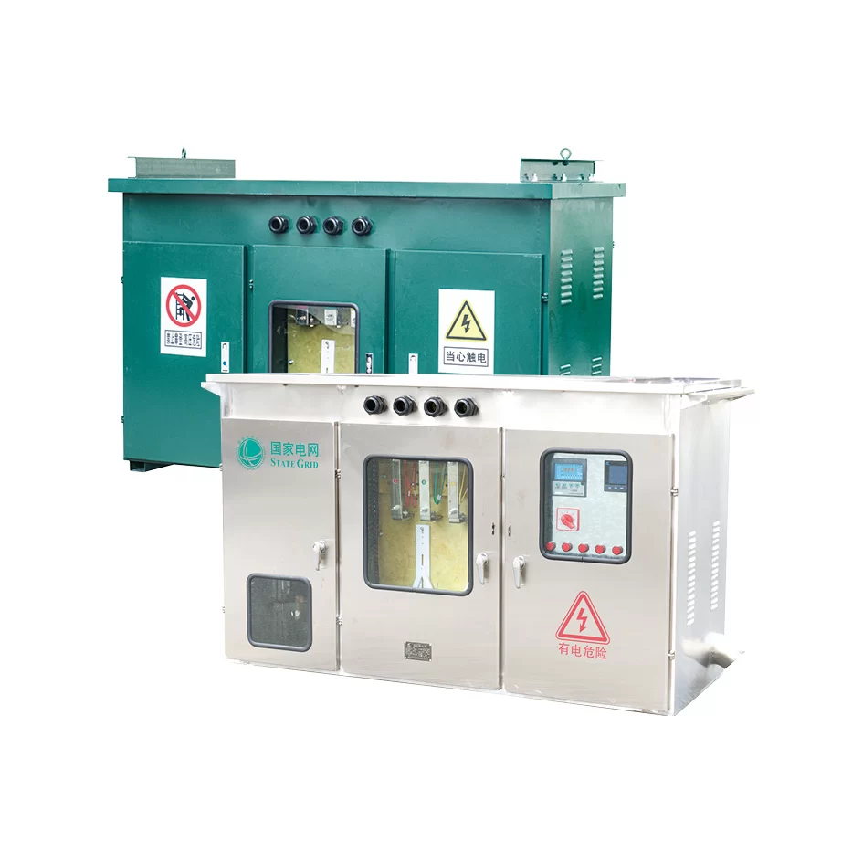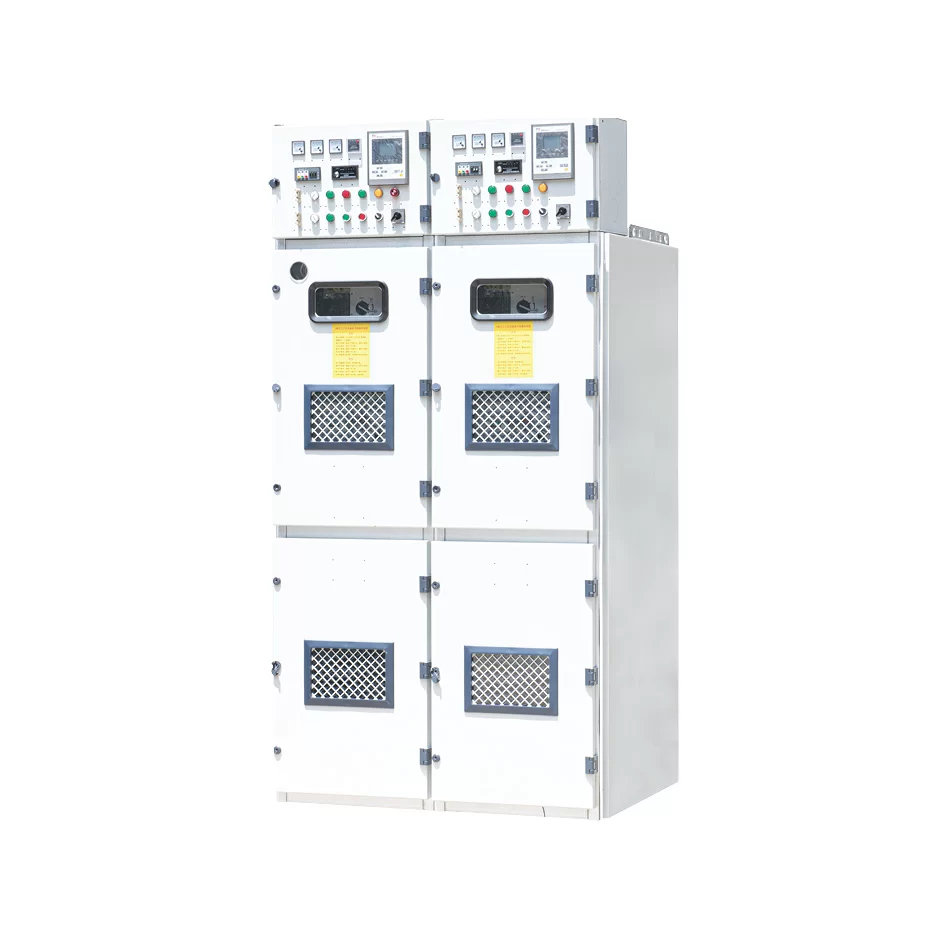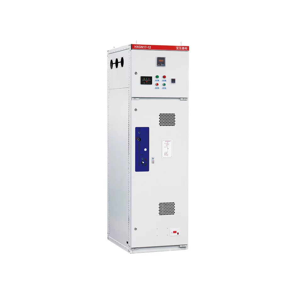
Product overview
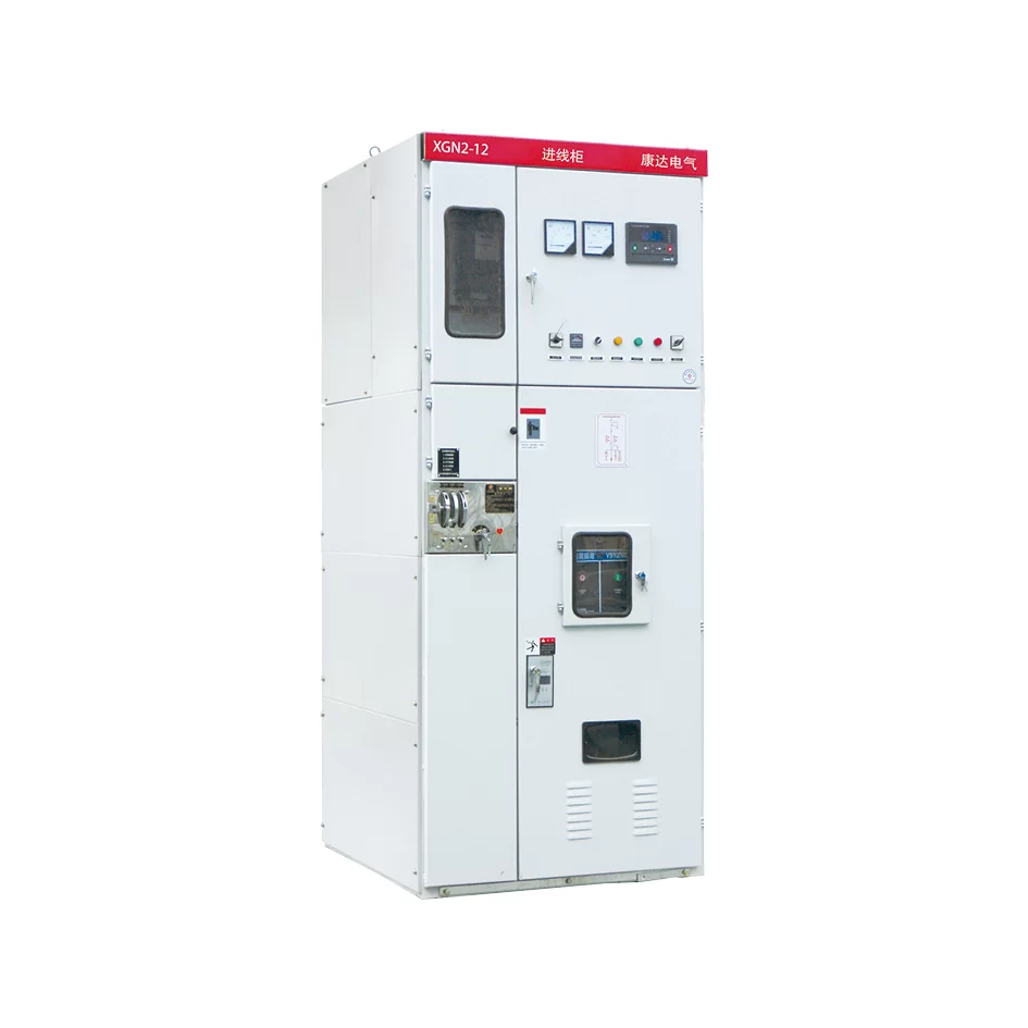
XGN2-12 box type fixed metal-enclosed switchgear (referred to as switchgear) is used for receiving and distributing electric energy in 3.6, 7.2 and 12KV three-phase AC 50Hz systems. It is suitable for occasions with frequent operations. Its bus system is a single bus (and can derive single bus with bypass and double bus structures). This switchgear meets the requirements of the national standard GB3906-91 A.C. Metal-Enclosed Switchgear for rated voltages of 3~35kV and the international standard IEC298, and has the “Pve prevention” locking function proposed by two ministries.
The main switch of this switchgear adopts ZN28-12 series vacuum circuit breaker, equipped with CD17 series electromagnetic operating mechanism or CT19 series spring operating mechanism, and the disconnecting switch adopts GN30-12 rotary disconnecting switch or GN22-12 high current disconnecting switch series products.
Model and meaning
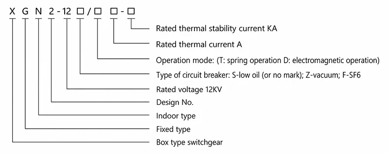
Service condition
● Ambient temperature: upper limit +40℃; lower limit -5℃;
● Altitude: no more than 1000m;
● Relative humidity: daily average value is not more than 95%, and monthly average value is not more than 90%;
● Seismic intensity: no more than 8 degrees;
● Places free from fire, explosion, serious pollution, chemical corrosion and violent vibration;
● Note: When ordering this product beyond the above conditions, please consult with our company.
Performance parameter
The technical data of the grounding switch and the technical parameters of the grounding switch shall be compatible with the parameters of the corresponding disconnector, so the dynamic and thermal stability current and contact pressure of the grounding switch shall be consistent with the corresponding disconnector, but the opening distance of the grounding switch shall not be less than 125mm.
| No. | Item | Unit | Technical parameter | |||||
|---|---|---|---|---|---|---|---|---|
| 1 | Rated voltage | kV | 3.6 | 7.2 | 12 | |||
| 2 | Rated current | A | 630~2500 | |||||
| 3 | Maximum operating current | A | 630 | 1000 | 1250 | 2000 | 2500 | 3150 |
| 4 | Rated breaking current | kA | 20 | 31.5 | ||||
| 5 | Rated thermal stability current | kA | 20 | 31.5 | ||||
| 6 | Rated dynamic stability current | kA | 50 | 80 | ||||
| 7 | Rated making current | kA | 50 | 80 | ||||
| 8 | Thermal stability time | s | 4 | |||||
| 9 | Degree of protection | IP2X | ||||||
| 10 | Bus grade | Single bus/single bus with bypass, Double bus | ||||||
| 11 | Operation mode | Electromagnetic/spring energy storage | ||||||
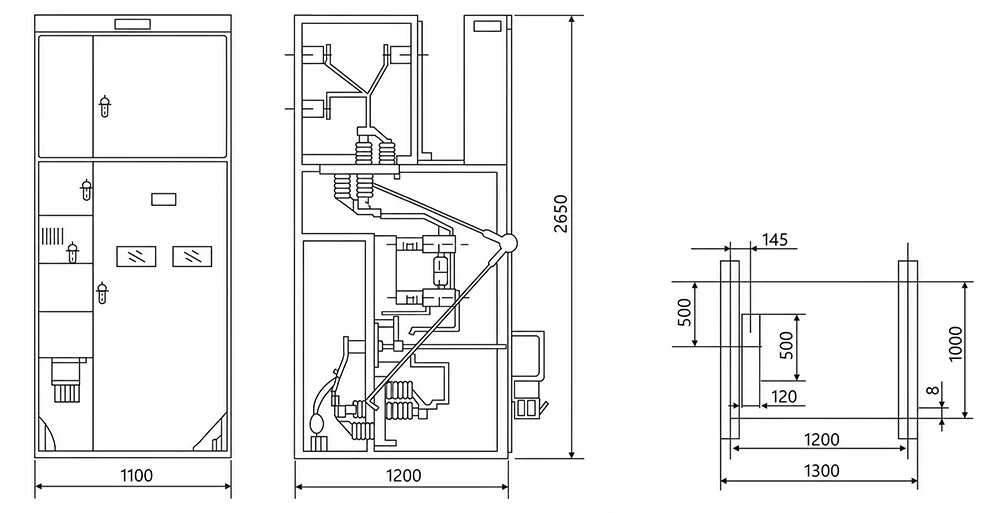
| 12 | Overall dimension (W×D×H) | mm | 1100×1200×2650 | |||||
| 13 | Weight | kg | Below 1000 | |||||
Shape and installation dimensions
Structure
The switchgear is a metal-enclosed box structure. The cabinet frame is welded by angle steel. The cabinet is divided into circuit breaker room, bus room, cable room and relay room. The rooms are separated by steel plates. The circuit breaker room is at the lower part of the cabinet, and the transmission of the circuit breaker is connected with the operating mechanism by the pull rod; the lower terminal of the circuit breaker is connected with the current transformer, the current transformer is connected with the terminal of the lower disconnecting switch, and the upper terminal of the circuit breaker is connected with the upper disconnecting switch.
There is no pressure release channel in the circuit breaker room. If the internal arc occurs, the gas can release the pressure through the exhaust channel.
The bus room is located at the upper rear part of the cabinet. In order to reduce the height of the cabinet, the bus is arranged in shape, supported by porcelain insulators with 7350N bending strength, and connected with the wiring terminal of the upper disconnector. The cable room is at the rear of the lower part of the cabinet. The support insulator in the cable room can be equipped with a monitoring device, and the cable is fixed on the bracket. If the upper connection is for interconnection, then this room is the cable interconnection room. The operating mechanism of the circuit breaker is installed at the right lower left position, and the upper part is the operating and interlocking mechanism of the disconnector.
The switch cabinet is maintained on both sides. The front is used to repair the secondary elements of the relay room, maintain the operating mechanism, mechanical interlocking and transmission parts, and repair the circuit breaker. The rear is used to repair the upper bus and cable terminals. The circuit breaker room and cable room are equipped with lights.
The lower part of the front is equipped with a grounding copper bus parallel to the width of the cabinet, with a cross section of 4*40mm2 for mechanical interlocking: to prevent on load opening and closing of the disconnector; to prevent false opening and closing of circuit breaker; to prevent entering the interval by mistake; to prevent the earthing switch from being energized; to prevent the grounding knife from closing. Corresponding mechanical interlocking shall be adopted for switch cabinet.
Ordering instruction
The user shall provide the following information when ordering:
● Main circuit solution number, primary system diagram and arrangement diagram;
● Secondary circuit wiring schematic diagram and terminal arrangement diagram. If there is no arrangement diagram for the terminal, the manufacturer’s regulations shall apply;
● Model, specification and quantity of electrical components in the switchgear;
● Material specifications of main bus and branch bus, otherwise, they shall be supplied according to the manufacturer’s regulations;
● The special environmental conditions for the use of switchgear shall be put forward when ordering;
● When accessories and spare parts are required, their types and quantities shall be noted.