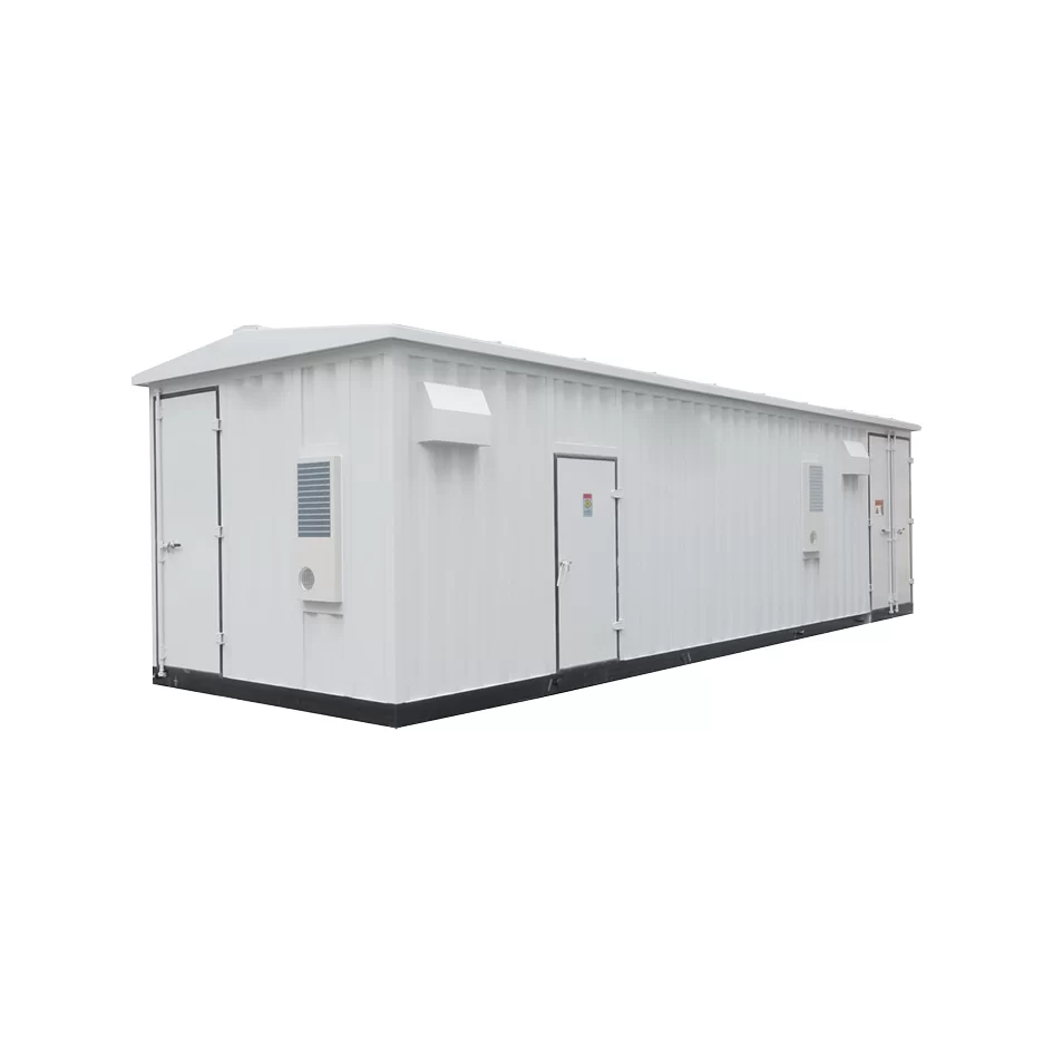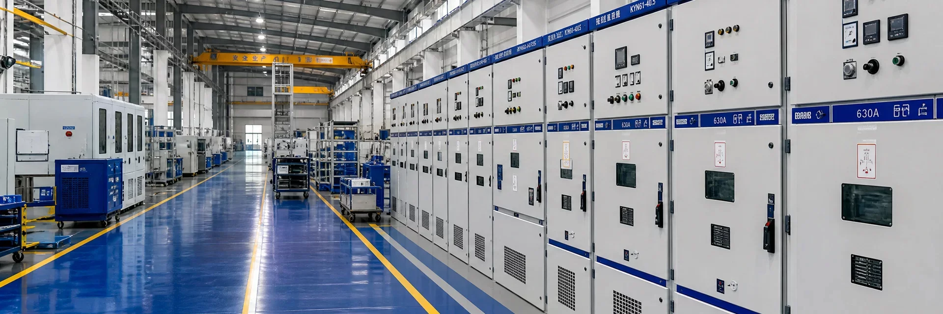
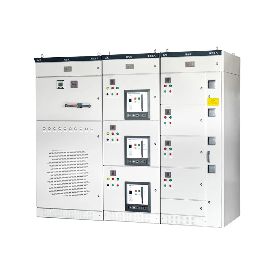
Application
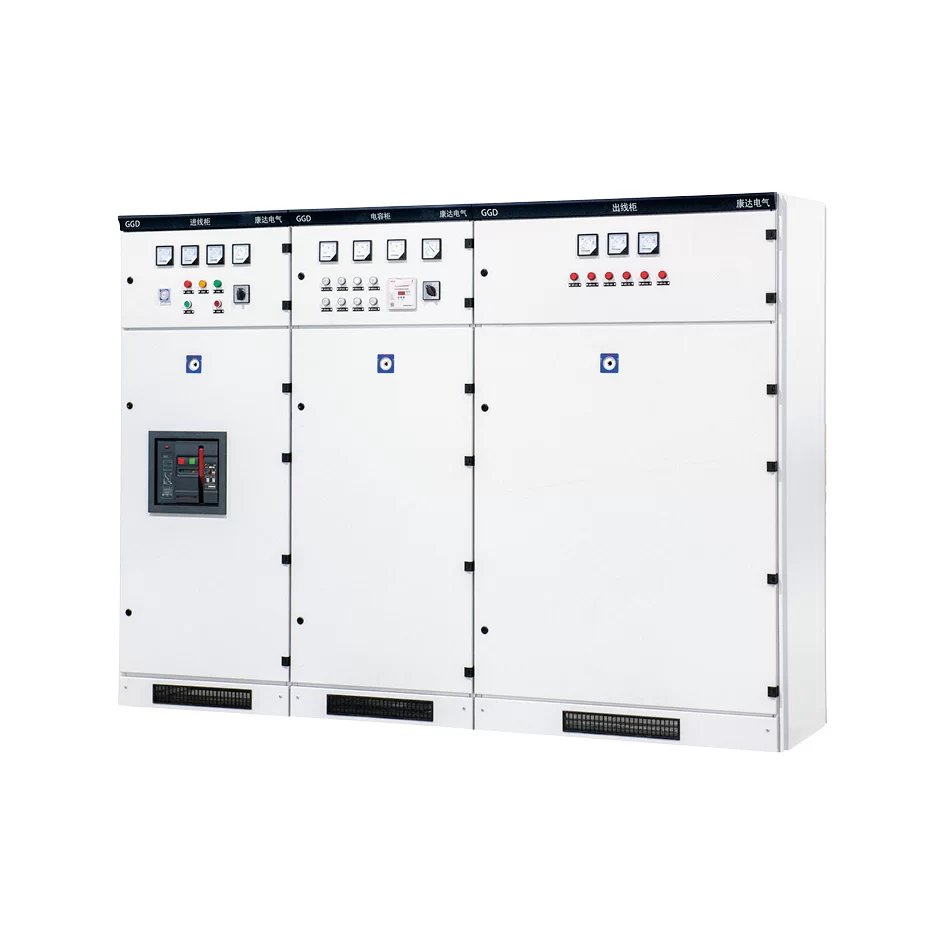
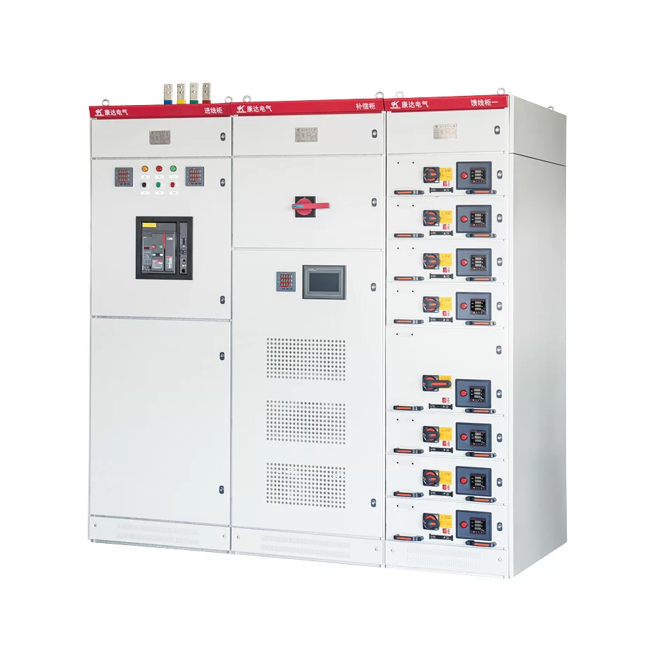
GCK low-voltage withdrawable switchgear consists of two parts: power distribution center (PC) switchgear and motor control center (MCC). It is suitable for power users applicable to such as power plants, substations, industrial and mining enterprises for AC 50Hz, maximum working voltage up to 660V, maximum working current up to 3150A in the power distribution system, it is used for power distribution, motor control, lighting and other power distribution equipment for their power conversion and distribution control.
Applicable environmental conditions
● The altitude does not exceed 2000m.
● The ambient air temperature is not higher than +40℃, and the average temperature within 24h is not higher than +35℃, and the ambient air temperature is not lower than -50℃.
● Atmospheric conditions: the air is clean, the relative humidity does not exceed 50% at +40℃, and higher relative humidity is allow-ed at lower temperatures, e.g.: 90% at +20℃.
● There place should be without Pre, explosion hazard, serious pollution, chemical corrosion and severe vibration.
● Inclination should not be more than 5° to the vertical.
● This product is suitable for transportation and storage at the following temperatures: -25℃ ~+55℃, and within a short period of time (not more than 24h) not exceeding +70℃.
● If the above service conditions cannot be met, the user should consult our company when ordering.
The main technical parameters of the switchgear
| Rated working frequency (Hz) | 50 | |
|---|---|---|
| Rated working voltage (V) | 380, 660 | |
| Rated insulation voltage (V) | 660 | |
| Rated working current (A) | Horizontal bus | 630-3150 |
| Vertical bus | 600 | |
| Rated short-time withstand current | Horizontal bus | 80kA (effective value) /1 second |
| Vertical bus | 50kA (effective value) /1second | |
| Rated peak withstand current | Horizontal bus | 176kA/0.1s |
| Vertical bus | 110kA/0.1s | |
| Main circuit connector (A) | 200, 400 | |
| Auxiliary circuit connector (A) | 10 | |
| Power frequency withstand voltage for 1 minute (V) | 2500 | |
| Protection level | IP40 | |
| Mode of operation | local, remote, automatic | |
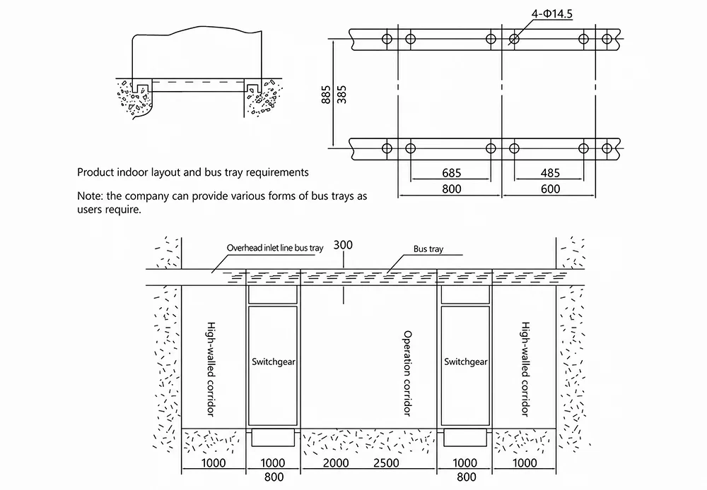
Installation dimensions and mounting holes
| Width for switchgear (A) | Depth for the switchgear (B) | Installation hole distance (a) | Installation hole distance (b) |
|---|---|---|---|
| 800 | 500 | 685 | 385 |
| 600 | 800 | 485 | 685 |
| 600 | 1000 | 485 | 885 |
| 800 | 800 | 685 | 685 |
| 800 | 1000 | 685 | 885 |
| 1000 | 800 | 885 | 685 |
| 1000 | 1000 | 885 | 885 |
Outline dimensions and installation dimensions
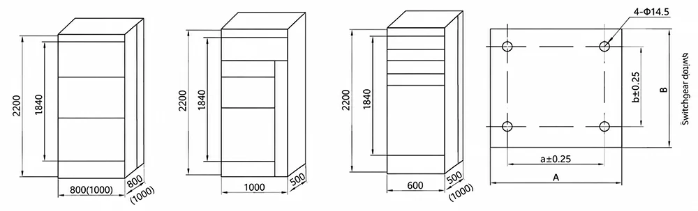
Schematic diagram of product installation foundation
Ordering instruction
● When this product is installed, the horizontal line between the switchgears should be connected Prrmly and reliably.
● The door of this product has an interlocking function with the main switch, that is, the door can be opened only when the power is cut off. The other side of the product is a screw sealing plate, which has no interlocking function with the main switch, therefore, the user must disconnect the power supply when disassembling the side panel of this product for maintenance.
● Non-professionals should not open the switchgear for maintenance and repair.