Main application
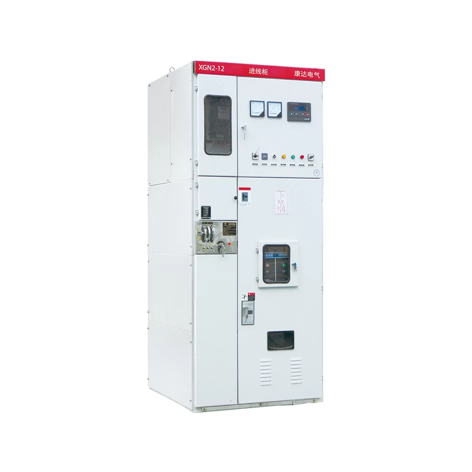
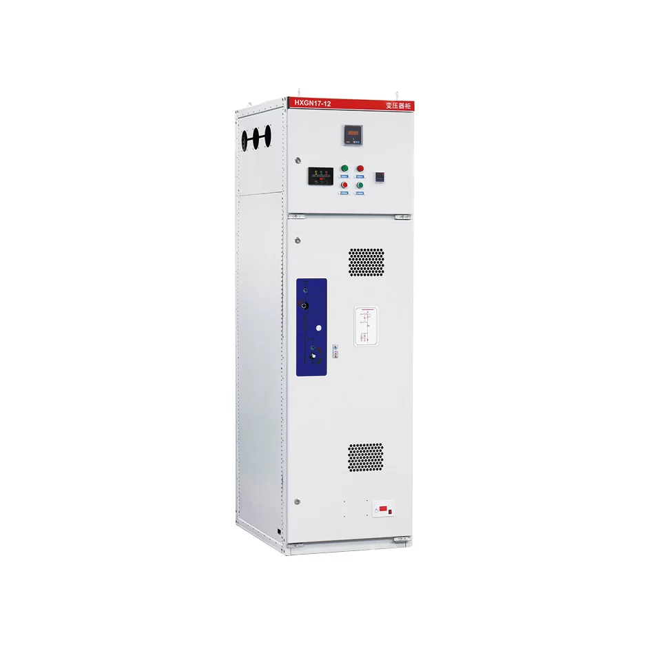
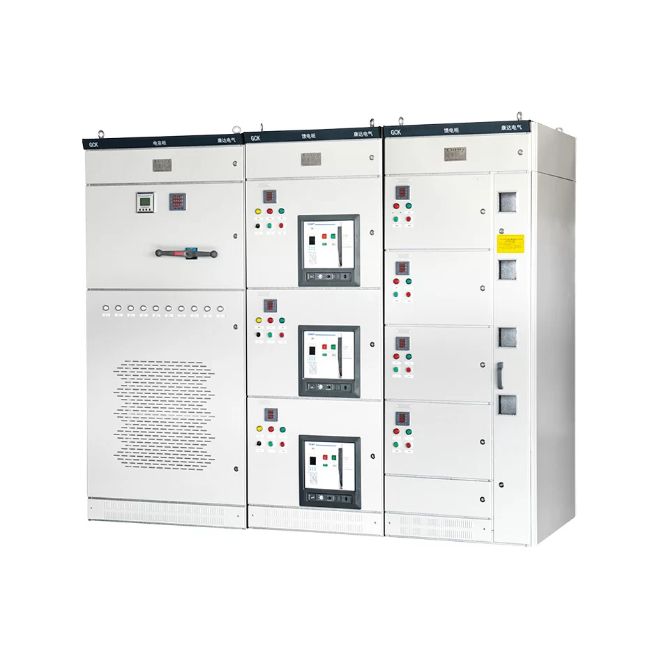
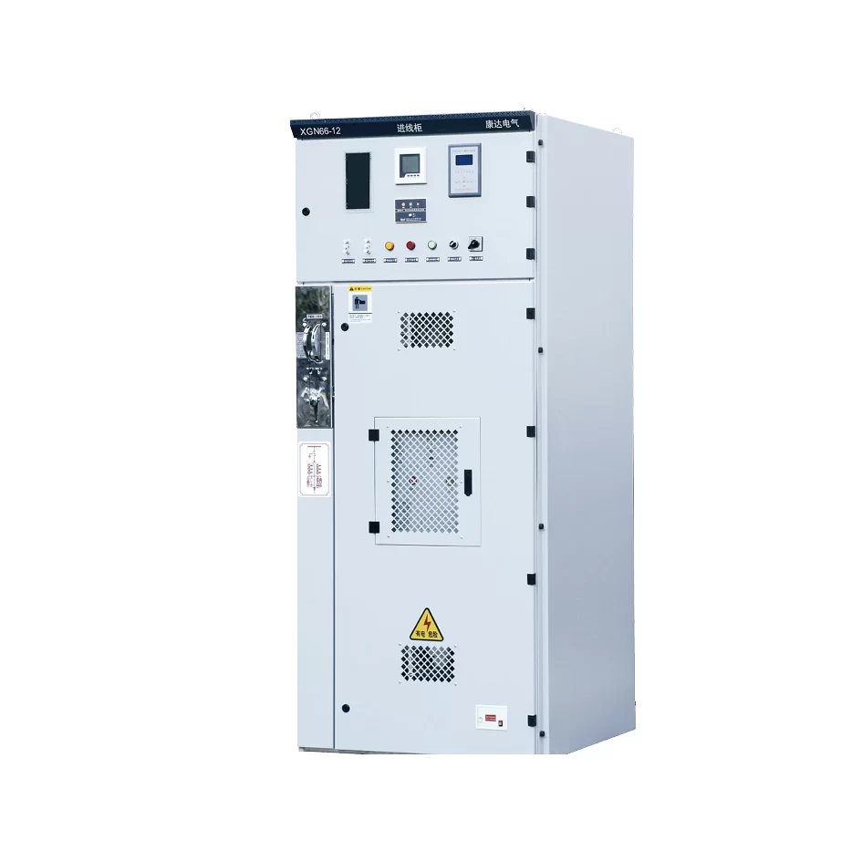
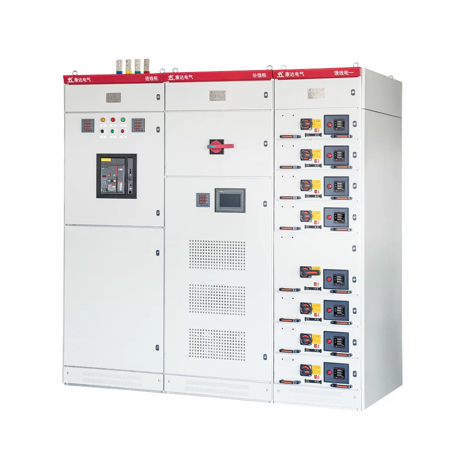
This series of low-voltage withdrawable switchgear is a kind of combined cabinet that is assembled by factory (FBA)with standard modules.
This series of low-voltage withdrawable switchgear is applicable to power plants, substations, petrochemical, metallurgical and steel rolling, transportation, energy, light industrial and textile enterprises, residential quarters, high-rise buildings and other places, as the power distribution equipment of the AC 50~60HZ power system with rated working voltage of 660V and below for power conversion, distribution and control.
The installation complies with GB 7251.1 Low-voltage switchgear and controlgear assemblies-Part 1: Type-tested and partially type-tested assemblies and JB/T 9961 Low-voltage withdrawable switchgear and controlgear assemblies and IEC439-1 international professional standards.
Model and meaning
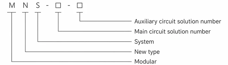
Normal service condition
● The ambient air temperature shall not be higher than +40°C and lower than -5°C , and the average temperature shall not be higher than +35°C within 24 hours.
● Atmospheric conditions: The air is clean and the relative humidity does not exceed 50% at the maximum temperature of +40°C. Higher relative humidity is allowed at lower temperatures, e.g. 90% at +20°C, but temperature changes should be taken into account as condensation may occur occasionally.
● Altitude: not exceeding 2000m.
● The device is suitable for transport and storage processes at temperatures ranging from -25°C to +55°C and up to +70°C for a short period of time (not exceeding 24h). The device should not suffer any irreversible damage at these limited temperatures and should be able to operate normally under normal conditions.
● If the above service conditions cannot be met, it shall be settled through negotiation between the user and the manufacturer.
● When the device is used on offshore oil drilling platform and nuclear power plant, a separate technical agreement shall be signed.
Basic technical parameter
| 1. Electric performance | 660V(1000)V | |
|---|---|---|
| Rated insulation voltage | 380V、660V | |
| Rated operating voltage | 5000A | |
| Max. operating current of main bus | 100kA/1s | |
| Rated withstand current of main bus | 220kA/1s | |
| Rated peak withstand current of main bus | 1000A | |
| Max. operating current of distribution bus (vertical bus) | ||
| Peak current of distribution bus (vertical bus) | ||
| Standard type | 105kA (max.) /0.1s | |
| Reinforced type | 176kA (max.) /0.1s | |
| 2. Protection level | |
|---|---|
| Standard | In line with IEC 529 and DIN 40050 standards |
| IP30 | Fixed protection for size greater than Φ 2.5 MM |
| IP40 | Fixed protection for size greater than 1.0 MM Φ |
| IP54 | protection against dust and any direction of spatter |
| Note | Please consult with the manufacturer when ordering IP54 protection level |
Switch cabinet type
1. Power distribution center cabinet (PC): it can use EMAX, MT, 3WN, AH, ME series circuit breaker.
2. Motor control center cabinet (MCC): it is assembled by drawers of different sizes. The main switch of each circuit adopts high-grade broken plastic case circuit breaker or rotating load switch with fuse.Power factor automatic compensation cabinet (with manual, automatic and remote power factor compensation device)
Cabinet body schematic diagram
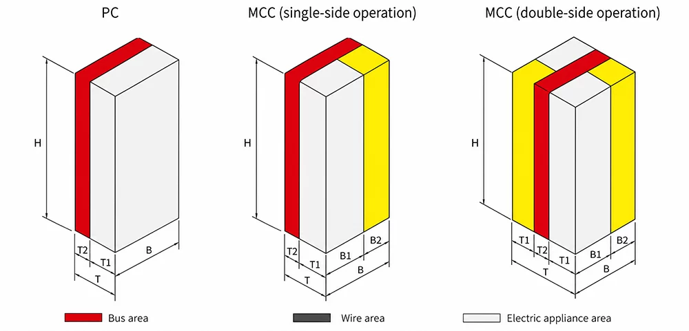
A power distribution center (PC) cabinet
| Height | Width | Depth | |||
|---|---|---|---|---|---|
| H | B | T | T1 | T2 | Note |
| 2200 | 400 | 1000 | 800 | 200 | Main bus transfer |
| 2200 | 400 | 1000 | 800 | 200 | Fₛ-1250-2000 ME630-1605 |
| 2200 | 600 | 1000 | 800 | 200 | F₂ₛ-2500 |
| 2200 | 800 | 1000 | 800 | 200 | F₄ₛ-3200 me2000-3200 |
| 2200 | 1000 | 1000 | 800 | 200 | F₅ₛ-4000 Me3205 |
| 2200 | 1200 | 1000 | 800 | 200 | Me4005 |
B Motor control center (MCC) cabinet Table
| Height | Width | Depth | Note | ||||
|---|---|---|---|---|---|---|---|
| H | B | B1 | B2 | T | T1 | T2 | |
| 2200 | 1000 | 600 | 400 | 600 | 400 | 200 | Single-side operation |
| 2200 | 1000 | 600 | 400 | 1000 | 400 | 200 | Double-side operation |
Combination mode diagram
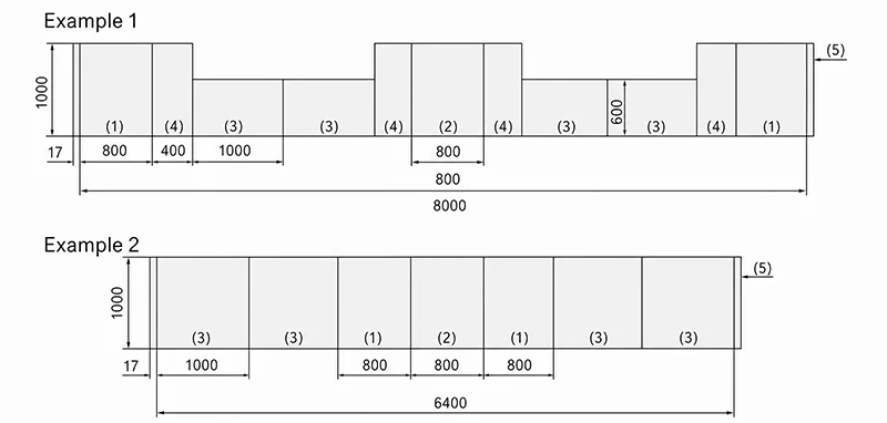
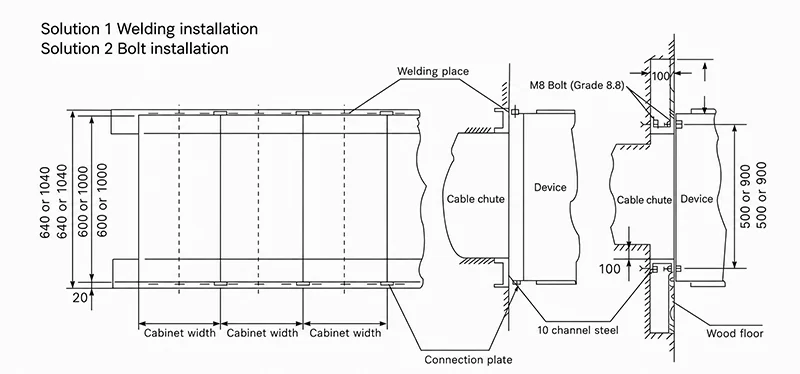
lnstallation diagram