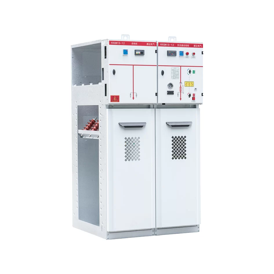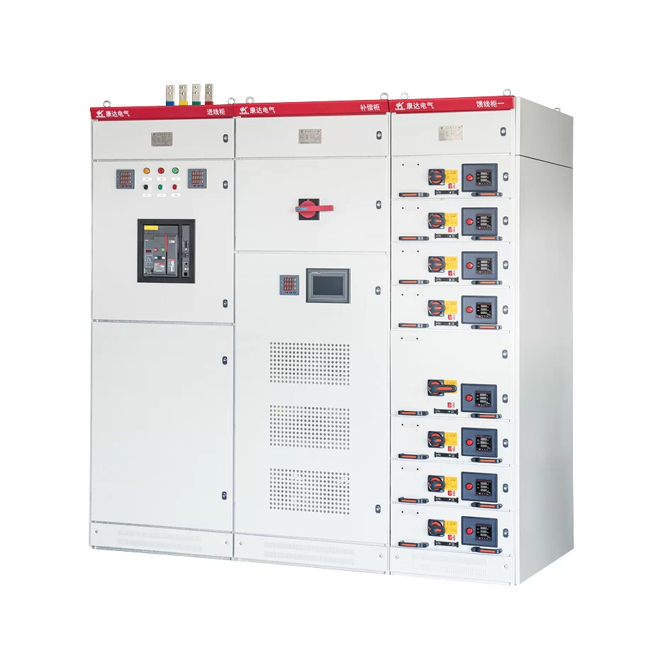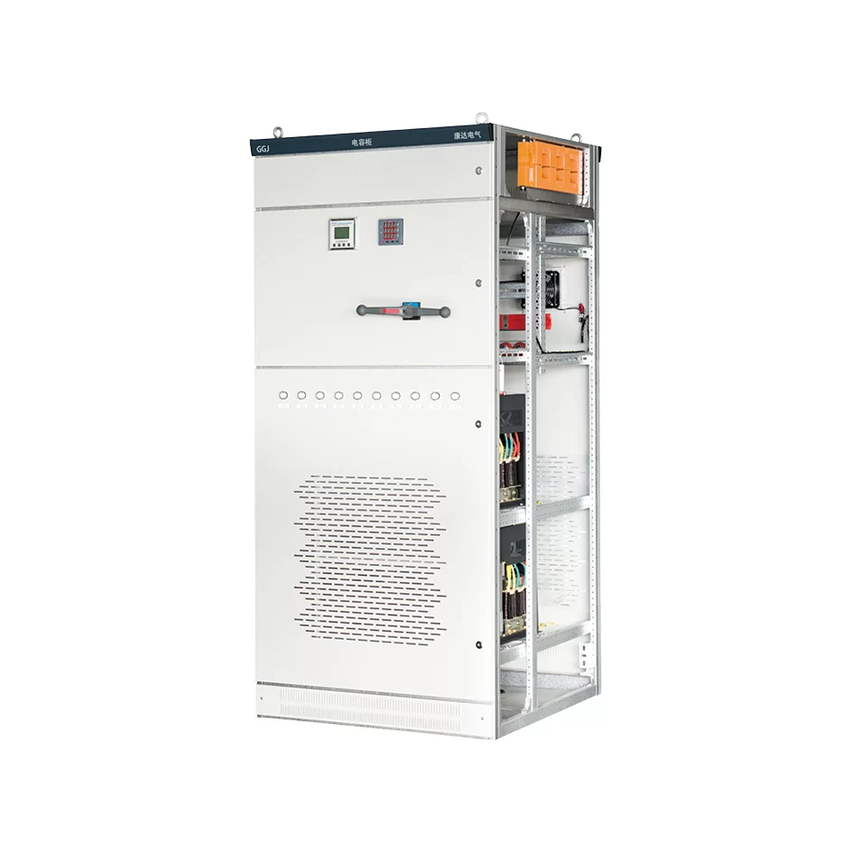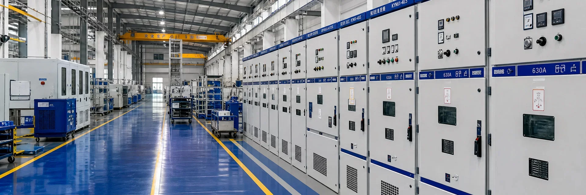
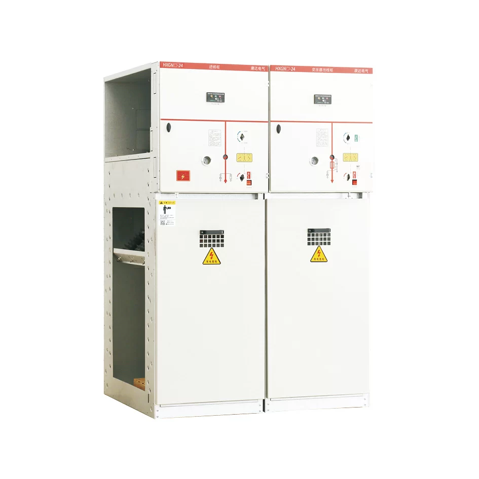
Product overview
● Increase the capacity of main transformer and improve the power supply capacity of substation.
● Improve the power transmission capacity of distribution lines and reduce the number of distribution lines.
● Increase the power supply radius of medium voltage lines.
● Improve the power supply quality of medium voltage power grid.
● Reduce the power loss of medium voltage power grid.
● Save nonferrous metals and land resources.
Model and meaning
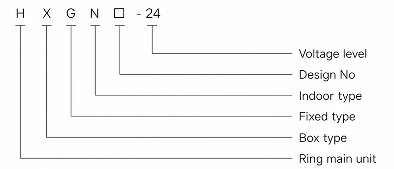
Service condition
● Altitude: ≤ 1000m;
● Ambient temperature: maximum ambient temperature +40℃, minimum ambient temperature -35℃, maximum daily temperature difference 25℃;
● Relative humidity: daily average relative humidity ≤ 95%, monthly average relative humidity ≤ 90%;
● Seismic intensity: 8 degree;
● Rated frequency of system: 50HZ;
● Annual leakage rate of SF6: ≤ 0.1%; enclosure protection grade: IP3X;
● Note: when ordering this product beyond the above conditions, please consult with our company.
Executive standard
● GB/T156 Standard voltages;
● GB 311.1 Insulation co-ordination-Part 1: DePnitions, principles and rules;
● GB 3804 3.6kV~40.5kV High-voltage alternating current switches for rated voltage above 3.6kV and less than 40.5kV
● GB 3906 Alternating-current metal-enclosed switchgear and controlgear for rated voltages above 3.6kV and up to and including 40.5kV;
● GB/T 11022 Common specfications for high-voltage switchgear and controlgear standards;
● GB/T 12,022 Sulfur hexafuoride for industrial use;
● GB16926 High-voltage alternating current switch-fuse combinations;
● DL/T 404 Indoor AC high voltage switchgear panel
Technical parameter
| No. | Name | Unit | Technical parameter | ||
|---|---|---|---|---|---|
| Load switch cabinet | Switch-fuse combination cabinet | ||||
| 1 | Rated voltage | kV | 24 | ||
| 2 | Rated frequency | Hz | 50 | ||
| 3 | Rated current | A | 630 | 125 | |
| 4 | Rated load breaking current | A | 630 | 125 | |
| 5 | Rated short-time withstand current (effective) (3s) | kA | 20 | ||
| 6 | Rated peak withstand current | kA | 50 | ||
| 7 | Closed loop breaking current | A | 630 | ||
| 8 | Maximum transfer current | A | 31.5 | ||
| 9 | Prospective short-circuit breaking current of fuse (effective) | kA | 1400 | ||
| 10 | 2s short time withstand current of grounding switch | kA | 20 | ||
| 11 | Rated current breaking times | Time | ≥ 100 | ||
| 12 | Mechanical life | Load switch | Time | ≥ 2000 | |
| Grounding switch | ≥ 2000 | ||||
| 13 | Annual leakage rate of SF6 gas | % | ≤ 0.1 | ||
| 14 | Rated short-time power frequency withstand voltage (effective) | Across isolating distance | kV | 64(79) | |
| Switch opening distance | kV | 64(79) | |||
| Phase to phase, phase to ground | kV | 50(65) | |||
| Rated lightning impulse withstand voltage (peak) | Across isolating distance | kV | 110(145) | ||
| Switch opening distance | kV | 110(145) | |||
| Phase to phase, phase to ground | kV | 95(125) | |||
| 15 | Temperature rise limit | K | According to GB/T 11022 | ||
| 16 | Operating mechanism | Manual, or electric plus manual | |||
| 17 | Operating voltage | V | recommended DC110, optional DC24 or AC48 AC220 | ||
| 18 | Creepage distance of insulating parts in cabinet | mm/kV | ≥ 20 (calculated as per 24kV) | ||
| 19 | Enclosure protection grade | IP3X | |||
| 20 | Clear air distance of bare conductor (phase to ground and phase to phase) | mm | ≥ 180 | ||
| 21 | Rated cable charging breaking current | A | 25 | ||
| 22 | Switching inductance current of no-load transformer | A | 0~15A | ||
| 23 | Opening and closing asynchrony | ms | <5 | ||
| 24 | Main circuit resistance (excluding fuse) | μΩ | <140 | ||
Note: The rated current of the switch-fuse combination is used for the complete combined apparatus of the load switch and the selected fuse. The data outside the brackets refer to the neutral point grounding system through low resistance, and the data inside the brackets refer to the neutral point grounding or ungrounded system through arc suppression coil.
Outline size
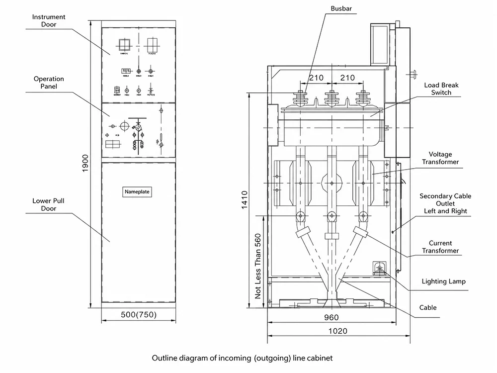
| Purpose of switch cabinet | Cabinet width(mm) | Cabinet depth (mm) | Cabinet height(mm) |
|---|---|---|---|
| Incoming cabinet | 750 | 1020 | 1900 |
| Outgoing cabinet | 500 | 1020 | 1900 |
| PT cabinet | 500 | 1020 | 1900 |
| Buscouple cabinet | 500 | 1020 | 1900 |
| Vice bus couple cabinet | 500 | 1020 | 1900 |
| Bus transition cabinet | 500 | 1020 | 1900 |
| Metering cabinet | 1120 | 1020 | 1900 |
Note:
1. The nominal depth of the switch cabinet includes all the outer edges of the door panel (excluding the convex elements, locks, pins, and the convex parts of the door panel);
2. The nominal height of the switch cabinet, including all the outer edges of the head (excluding convex rings)